
We took our G-Force wall blocks to NCMA and performed 3 different tests on them: absorption, freeze-thaw durability and grid pullout.
Absorption
Here’s how an absorption test is performed.
STEP 1: Make sure the block is free of dust and debris.
STEP 2: Measure its weight with a scale
STEP 3: Immerse the block in water. Lay it on a scale inside the bath.
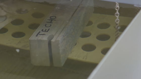
STEP 4: Take note of the new weight.
As water infiltrates the block, it becomes heavier. The difference between the original weight and the weight of the block once it is immersed in water helps us determine its absorption rate. The industry specification is for less than 5% absorption.
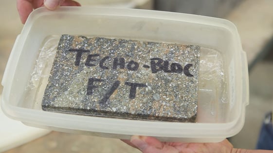
Freeze-thaw Durability
The ASTM C1262 freeze-thaw durability test method covers the resistance to freezing and thawing of dry-cast segmental retaining wall units (see ASTM C1372).
We tested our G-Force block in a 3% saline solution to evaluate its resistance to de-icing salts as well.
Here are the steps.
STEP 1: Immerse the block in a container filled with a 3% saline solution.
STEP 2: Put the container in a freezer set to -5 °F (-20 °C) for a few hours. Then, gradually increase the temperature back up, above freezing, to thaw it.
STEP 3: Repeat this cycle 100 times.
STEP 4: The lab technician will calculate the mass lost during this process. Mass is lost due to the expansion and contraction of the water-soaked concrete. The mass lost should not exceed 1% across five individual test pieces after 100 cycles.
Our block performed well under these conditions, proving its resistance to freeze-thaw cycles and road salts. This performance contributes to its long-term durability and aesthetic.
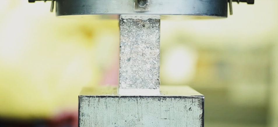
Grid Pullout
This test method is used to determine the connection properties between a layer of geosynthetic reinforcement and segmental retaining wall blocks.
It permits the measurement of the connection strength of the system under varying loads.
Here’s how it’s done.
STEP 1: Insert the units in the machine and fill the voids of the blocks with stone, like it would be installed on the field.
STEP 2: Add a geogrid fabric between the rows of blocks.
STEP 3: Adjust the hydraulic cylinders. Once activated, they simulate a wall height load, as opposed to stacking more blocks on top of the units.
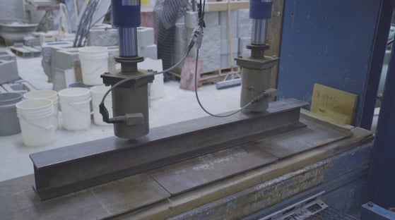
STEP 4: The machine pulls the grid out from between the units.
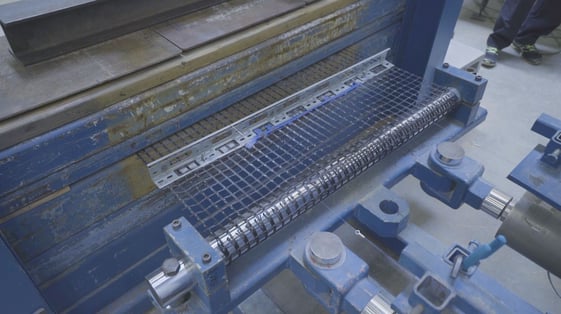
The connection strength is measured as the grid is pulled out under various loads. This data helps us design SRW systems correctly and safely.
BUILDING A WALL THAT NEEDS REINFORCEMENT, BUT CAN'T FIND WHAT YOU NEED IN THE TECHO-SPEC GUIDE?
CHECK OUT OUR